Overview
My first simple project was having 1 XBee (the coordinator in API mode) talking serial to an arduino. The second XBee (the router in AT mode) would be reading a state of a pin and reporting its value every second. It would send that information to the coordinator and the coordinator would send it to the arduino where it can be seen via the serial monitor. A contrived setup and test of the XBee, but yet it made me have to learn a few more things and research on how it works.
 |
| XBee #1 - the controller in API mode |
 |
| XBee #2 - the router in AT mode |
The XBee #2 (router) is hooked up to an arduino solely for power and is not using any other features on the arduino. The XBee's I/O pin has been configured (via X-CTU) to read the state of the pin every second. To change the state, I have a momentary push button and a LED wired in. Pushing the button will cause the pin to read HIGH and the LED to go on. Releasing the button will cause the pin to read LOW and the LED to go off. Here are a few more pictures to illustrate.


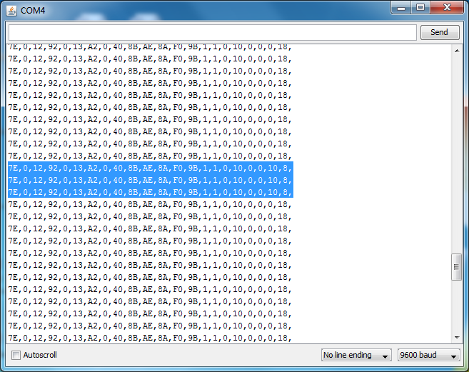
Understanding the data
I have the arduino (XBee #1 controller) programmed to write out the frame that the XBee #2 (router) sent to it. By analyzing the frame (of hex values) we can see the digital pin being toggled as well. The highlighted lines second to the last byte (0x10) shows that digital pin 4 read high. Why 0x10 you ask? That is because bytes 19 and 20 represent the digital pin data. byte 20 represents 8 digital pins with bit 0 corresponding to digital pin 0 and bit 7 to digital pin 7. So, 0x10 (16 decimal) is 10000 in binary which tells us that digital pin 4 is reading high.
 |
| State of digital pin changed |
Hi i like your tutorial with this configuration where the coordinator is in API mode and the router in AT mode. At the moment i have a problem where i have a same configuration. I beg you if you can send me the sketches that you uploaded on the Arduino boards, and trying to create an ideea in how to continue a personal project. please help me in this.Best regards
ReplyDeleteFrancu, sorry i forgot to look for these sketches, but i'll try to get you something this weekend. or were you able to move past the issues you were having?
ReplyDelete