Showing posts with label arduino. Show all posts

Saturday, July 5, 2014

GPS with OLED

Wow, it's been a while since I've made a post... I've been playing around with the the Adafruit GPS for a while now as well as messing with different OLED's as well. I came across a board from @mikerankin that combined both into one with an Arduino Pro Mini. AVR programming has also been taking a lot of my spare time and so I thought this would be a great project to consolidate everything I've learned so my goal was to write native C code compiled with avr-gcc and upload it to the board with avrdude instead of using the Arduino IDE (though that works with this board and would be much easier; but where's the challenge there!). Here are a few pics from the work in progress...

These pictures show the main screen and the board itself. Upper left corner is the temperature reading, upper right is the number of satellites that the GPS receiver is connected to. Bottom shows the format of the time (12h or 24h format is supported). Bottom right is the date and in the middle is the time.

This picture shows the trip summary as it tracks distance much like an odometer of a car. I changed the distances from metric to US measurements, but forgot to change the labels accordingly (oops! I know what I'll be doing after I post this)
This next screen shows the altitude (upper left), number of satelliets (upper right), course (below number of satellites) and speed in miles per hour.
This is the back of the GPS Board and you can see the Atmega 328 microprocessor , FTDI chip, resistors, LEDs, etc. You can refer to Mike Rankin's page for schematics and other details.

These pictures show the status LED for the lipo battery (red is charging and green is charged).

Lastly, this is a side view of the board. You can see the GPS module that the OLED hovers above on.

There are many more features that I have not discussed (ie. resetting the trip meter, saving a lat/lon position, saving data, etc). Those are all included in the original sketch which was done by Karman and posted to his blog. However, that sketch didn't work out of the box for me and kept crashing. I've since modified it to toggle between metric and US measurements, fix the crashing bug, and a few other minor fixes with some graphics and font modifications.

Monday, September 2, 2013

Simple Xbee Tutorial

I also got a few XBee modules with USB XBee Adapters and I started to mess around with them. The reason I got the adapters is primarily two fold. First, the XBee pins are 2mm and not the standard 0.1" so they do not fit on the standard breadboard. Secondly, the USB adapter makes programming the XBee very simple. I am using X-CTU to do the programming, but you can also do it over command line using the terminal, but it's a little more complicated.

Overview
My first simple project was having  1 XBee (the coordinator in API mode) talking serial to an arduino. The second XBee (the router in AT mode) would be reading a state of a pin and reporting its value every second. It would send that information to the coordinator and the coordinator would send it to the arduino where it can be seen via the serial monitor. A contrived setup and test of the XBee, but yet it made me have to learn a few more things and research on how it works.


XBee #1 - the controller in API mode
XBee #2 - the router in AT mode


The XBee #2 (router) is hooked up to an arduino solely for power and is not using any other features on the arduino. The XBee's I/O pin has been configured (via X-CTU) to read the state of the pin every second. To change the state, I have a momentary push button and a LED wired in. Pushing the button will cause the pin to read HIGH and the LED to go on. Releasing the button will cause the pin to read LOW and the LED to go off. Here are a few more pictures to illustrate.

Understanding the data
I have the arduino (XBee #1 controller) programmed to write out the frame that the XBee #2 (router) sent to it. By analyzing the frame (of hex values) we can see the digital pin being toggled as well. The highlighted lines second to the last byte (0x10) shows that digital pin 4 read high. Why 0x10 you ask? That is because bytes 19 and 20 represent the digital pin data. byte 20 represents 8 digital pins with bit 0 corresponding to digital pin 0 and bit 7 to digital pin 7. So, 0x10 (16 decimal) is 10000 in binary which tells us that digital pin 4 is reading high.
State of digital pin changed

Sunday, September 1, 2013

TFT Display

Wow, I'm so far behind with this blog! I recently got a 2.2" 18-bit color TFT Display and hooked it up to my arduino to see what the demo looks like. Quite impressive! Especially coming from a monochrome 128x64 display! To get it working using the arduino was very straight forward and simple. I want to use this with my Raspberry Pi so the next step would be to make my own C++ driver to talk to the ILI9340 chip on the TFT. Granted, not all the functionality that the arduino library will be supported, as I just to display text and a few graphics (PNG or BMP). The TFT board also has a mini sd card slot so you could store pictures or data on there that is to be displayed. Check out the link about for all the specifications for the board.

Here are a few pictures from the arduino demo.

Sunday, August 4, 2013

Serial communication with Arduino

Been a bit busy and this is long overdue... Here is an example of serial communication between the Arduino and a computer. In this example, I'll use python to send data over the serial port. The arduino will listen and if it gets the right data, it will light up the RGB LED. Here is how things are wired.
I have the green pin connected to digital pin 7, the blue pin connected to digital pin 5, and the red pin connected to digital pin 3 on the arduino. One pin of the RGB LED is connected to ground. Please check your LED leads to see which is your ground pin. I also have 3 220 ohm current limiting resistors wired in. Nothing too special here... For the Arduino code, I have things driven from the serial communication. Based on what it receives, it will light up the appropriate LED color. For example, if "red" is received, the LED will light up red. If "blue" is received, it will light the LED in blue.


#!/usr/bin/env python

import serial
import sys

if (len(sys.argv) > 1):
    ser = serial.Serial('/dev/tty.usbmodem1421', 9600)
    bytesWritten = ser.write(sys.argv[1])
    print ("bytes written: " + str(bytesWritten))

The python script basically sends the first parameter to the serial port. In my case, the serial port i'm sending data to is /dev/tty.usbmodem1421 (this is my aruduino). The arduino acts upon 3 commands and they are "red", "green", and "blue." Anything other than those 3 commands are ignored. Here is the arduino code.
#include 

const int GREEN_PIN = 7;
const int BLUE_PIN = 5;
const int RED_PIN = 3;

int incomingByte = 0;
char buf[16];

void setup ()
{
  Serial.begin(9600);
  pinMode(GREEN_PIN, OUTPUT);
  pinMode(BLUE_PIN, OUTPUT);
  pinMode(RED_PIN, OUTPUT);

  digitalWrite(GREEN_PIN, LOW);
  digitalWrite(BLUE_PIN, LOW);
  digitalWrite(RED_PIN, LOW);
  memset(buf, '\0', sizeof(buf));
}

void loop ()
{
  if (readColorFromSerial())
  {
    if (strcmp (buf, "red") == 0)
    {
      // change led to red
      Serial.println ("changing LED to red");
      lightLED(RED_PIN);
    }
    else if (strcmp (buf, "green") == 0)
    {
      // change led to green
      Serial.println ("changing LED to green");
      lightLED(GREEN_PIN);
    }
    else if (strcmp (buf, "blue") == 0)
    {
      // change led to blue
      Serial.println ("changing LED to blue");
      lightLED(BLUE_PIN);
    }
    else
    {
      Serial.print("Invalid input '");
      Serial.print(buf);
      Serial.println("' - expected red, green, or blue");
    }
  }
}

int readColorFromSerial()
{
  if (Serial.available())
  {
    memset(buf, '\0', sizeof(buf));
    Serial.readBytesUntil('\n', buf, sizeof(buf));
    return 1;
  }
  return 0;
}

void lightLED(int pin)
{
  switch (pin)
  {
  case RED_PIN:
    digitalWrite(GREEN_PIN, LOW);
    digitalWrite(BLUE_PIN, LOW);
    digitalWrite(RED_PIN, HIGH);
    break;
  case GREEN_PIN:
    digitalWrite(BLUE_PIN, LOW);
    digitalWrite(RED_PIN, LOW);
    digitalWrite(GREEN_PIN, HIGH);
    break;
  case BLUE_PIN:
    digitalWrite(RED_PIN, LOW);
    digitalWrite(GREEN_PIN, LOW);
    digitalWrite(BLUE_PIN, HIGH);
    break;
  }
}

After compiling and uploading the sketch to the aruduino, we execute the python script.


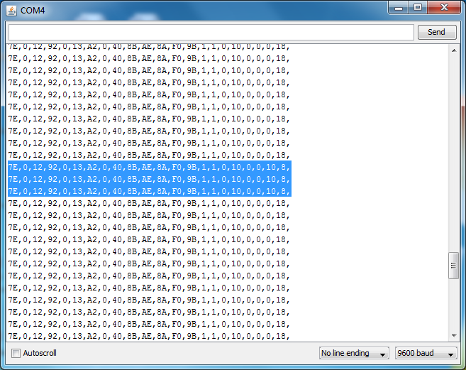
If you open the serial monitor on the aruduino, you can see what the aruduino is doing. Here is a sample screenshot.

Here are the results you should see with respect to the LED.
Next up, using PWM to control the brightness of the LED of each color. Hopefully I can get this next blog post up within a few days...