Here are mine after I soldered the headers on and wired them up on bread board.
Saturday, June 20, 2015
Raspberry Pi and Temperature Sensors
I just got 2 temperature sensors from Adafruit.
They were very easy to use and didn't take much coding to get them up and running. They are both I2C and I was able to use my existing libraries to talk to them from the PI. I did put up code on github to show how to retrieve the temperature from both. The BMP180 has a few more things (ie. pressure, altitude, etc.) Though, the altitude wasn't very accurate to where I am. I am not sure about the pressure as I am not familiar with that... Either way, a fun project to get up and running!
Pi user space SPI
I finally had some time to play with a OLED (same one as my I2C one; SSD1306 chip), but this interface was SPI. I wanted to learn more about SPI and write a user space program in C++ that would run on my Raspberry Pi and drive the SPI OLED just like I had done for my I2C OLED. Did some digging on spidev and learned a lot. The commands to the OLED were the same as the I2C so I did not have to re-invent the wheel there, but the communication was the only difference.
Saturday, November 22, 2014
Emulating a HID Device
I've been hacking around with some Atmel microcontrollers and I thought I've give this project a try. Due to circumstances out of my control, taking a pedometer to work is not possible as it is not permitted on site. However, this pedometer is directly related to a health fund that gets money from my employer based on how active you are. I've already done something like this:
Yes, it get the job done, but at the expense of time... So, now I am going one step further. Using either a Pro Trinket or Teensy (images below), I was planning on faking things out. Instead of plugging this into my computer
I'll plug this in! :)
The next step was to setup setup the boards to emulate the USB HID device. For the Pro Trinket, I used VUSB and for the Teensy, I used LUFA. The VUSB API was a bit more involved and took a bit longer to get working as documentation seems sparse from my searches. Using Dean's LUFA library, it was very easy to setup and get configured. Since the Pro Trinket uses a slightly less sophisticated microprocessor (ATmega 328p), there is no USB support in that chip. However, Teensy's chip is the ATmega 32U4 which does have USB support and can use the LUFA stack. Either way, I thought I'd give both a shot.
After getting both configured, if I run the 3rd party software provided by Virgin Healthmiles, it now thinks I've plugged in the "real" pedometer. First step done! Drink a few beers and celebrate!
The next step is where I am currently stuck... Decoding their USB protocol. I have uploaded data many times using the real pedometer and captured the USB communication. Here is some sample data.
I've tried sending back the data I captured (using wireshark), but no dice. So they have some smarts built in, but I can't pinpoint it just yet. To complicate things more, the 3rd party software only supports Windows and Mac. Mac has good tools, but nothing to capture USB! I've tried to setup a VM on my linux box, but wine does not support all win32 API's the 3rd party software is calling. So I am writing the code on linux, uploading with avrdude and testing on Windows. Fun times.... Perhaps I should bit the bullet and install the development environment on windows. talk about humbug!
So.... my question for some of you readers out there. What are some common techniques used for this? What are things I can try to decode the data? My serial number seems to be encoded in the data, but I have yet to figure it out as things are either encrypted or on the bit fields and not at the byte boundaries. Any one have advice/suggestions as I'm all ears! Even better.... anyone want to join me with this project?!
I'll plug this in! :)
The next step was to setup setup the boards to emulate the USB HID device. For the Pro Trinket, I used VUSB and for the Teensy, I used LUFA. The VUSB API was a bit more involved and took a bit longer to get working as documentation seems sparse from my searches. Using Dean's LUFA library, it was very easy to setup and get configured. Since the Pro Trinket uses a slightly less sophisticated microprocessor (ATmega 328p), there is no USB support in that chip. However, Teensy's chip is the ATmega 32U4 which does have USB support and can use the LUFA stack. Either way, I thought I'd give both a shot.
After getting both configured, if I run the 3rd party software provided by Virgin Healthmiles, it now thinks I've plugged in the "real" pedometer. First step done! Drink a few beers and celebrate!
The next step is where I am currently stuck... Decoding their USB protocol. I have uploaded data many times using the real pedometer and captured the USB communication. Here is some sample data.
I've tried sending back the data I captured (using wireshark), but no dice. So they have some smarts built in, but I can't pinpoint it just yet. To complicate things more, the 3rd party software only supports Windows and Mac. Mac has good tools, but nothing to capture USB! I've tried to setup a VM on my linux box, but wine does not support all win32 API's the 3rd party software is calling. So I am writing the code on linux, uploading with avrdude and testing on Windows. Fun times.... Perhaps I should bit the bullet and install the development environment on windows. talk about humbug!
So.... my question for some of you readers out there. What are some common techniques used for this? What are things I can try to decode the data? My serial number seems to be encoded in the data, but I have yet to figure it out as things are either encrypted or on the bit fields and not at the byte boundaries. Any one have advice/suggestions as I'm all ears! Even better.... anyone want to join me with this project?!
Wednesday, July 30, 2014
Github!
Finally got around to posting some code to github... long overdue!
https://github.com/kamaaina/cpp-projects
Saturday, July 5, 2014
GPS with OLED
Wow, it's been a while since I've made a post... I've been playing around with the the Adafruit GPS for a while now as well as messing with different OLED's as well. I came across a board from @mikerankin that combined both into one with an Arduino Pro Mini. AVR programming has also been taking a lot of my spare time and so I thought this would be a great project to consolidate everything I've learned so my goal was to write native C code compiled with avr-gcc and upload it to the board with avrdude instead of using the Arduino IDE (though that works with this board and would be much easier; but where's the challenge there!). Here are a few pics from the work in progress...
These pictures show the main screen and the board itself. Upper left corner is the temperature reading, upper right is the number of satellites that the GPS receiver is connected to. Bottom shows the format of the time (12h or 24h format is supported). Bottom right is the date and in the middle is the time.
This picture shows the trip summary as it tracks distance much like an odometer of a car. I changed the distances from metric to US measurements, but forgot to change the labels accordingly (oops! I know what I'll be doing after I post this)
This next screen shows the altitude (upper left), number of satelliets (upper right), course (below number of satellites) and speed in miles per hour.
This is the back of the GPS Board and you can see the Atmega 328 microprocessor , FTDI chip, resistors, LEDs, etc. You can refer to Mike Rankin's page for schematics and other details.
These pictures show the status LED for the lipo battery (red is charging and green is charged).
Lastly, this is a side view of the board. You can see the GPS module that the OLED hovers above on.
There are many more features that I have not discussed (ie. resetting the trip meter, saving a lat/lon position, saving data, etc). Those are all included in the original sketch which was done by Karman and posted to his blog. However, that sketch didn't work out of the box for me and kept crashing. I've since modified it to toggle between metric and US measurements, fix the crashing bug, and a few other minor fixes with some graphics and font modifications.
These pictures show the main screen and the board itself. Upper left corner is the temperature reading, upper right is the number of satellites that the GPS receiver is connected to. Bottom shows the format of the time (12h or 24h format is supported). Bottom right is the date and in the middle is the time.
This picture shows the trip summary as it tracks distance much like an odometer of a car. I changed the distances from metric to US measurements, but forgot to change the labels accordingly (oops! I know what I'll be doing after I post this)
This next screen shows the altitude (upper left), number of satelliets (upper right), course (below number of satellites) and speed in miles per hour.
This is the back of the GPS Board and you can see the Atmega 328 microprocessor , FTDI chip, resistors, LEDs, etc. You can refer to Mike Rankin's page for schematics and other details.
These pictures show the status LED for the lipo battery (red is charging and green is charged).
Lastly, this is a side view of the board. You can see the GPS module that the OLED hovers above on.
There are many more features that I have not discussed (ie. resetting the trip meter, saving a lat/lon position, saving data, etc). Those are all included in the original sketch which was done by Karman and posted to his blog. However, that sketch didn't work out of the box for me and kept crashing. I've since modified it to toggle between metric and US measurements, fix the crashing bug, and a few other minor fixes with some graphics and font modifications.
Saturday, March 22, 2014
ATtiny85 and V-USB on a breadboard
Using an ATTiny85 chip, I programmed it to emulate a USB device and stuck it on a breadboard with a mini USB breakout board. It's not the nicest layout on a breadboard, but it gets the job done. Plugging the USB cable into the computer, it runs the code and a USB slave device shows up. I have a custom driver communicating with the chip over USB.
Thursday, March 6, 2014
Trinket with V-USB
A few months ago I stumbled upon Joonas Pihlajamaa's tutorial about AVR ATtiny USB Tutorial. His tutorial is very informative and got me interested in communicating with AVR chips via USB. In his tutorial, he used an ATtiny2313 chip on a breadboard with different components to demonstrate things. Since, I'm not an electrical engineer and don't know too much about putting all that together I didn't pursue his setup.
In came Adafruit's Trinket which is conveniently mounted on a PCB and has a USB interface with a ATtiny85 chip. I then set out to try to replicate his tutorial on this hardware. I didn't know much about avr-gcc so I got to learn about that in the process. In my prior post, I detailed out how to setup your environment, compile a simple program, and upload it to the trinket so refer to that if you are reading this first.
A lot of the magic happens in the V-USB library which does most of the heavy lifting for us. Since the ATtiny85 doesn't have a USB stack on that chip, we must use this library and software to emulate it. The configuration from Joonas' tutorial was a bit different as port's and pins differ between the ATtiny2313 and ATtiny85. 99% of the code is already listed in his tutorial so I am not going to re-invent the wheel here as you can refer to his tutorial for the code. Here is the hex file you will need to upload to the trinket. Using his usbtest binary, you can interface with your trinket over USB!
In came Adafruit's Trinket which is conveniently mounted on a PCB and has a USB interface with a ATtiny85 chip. I then set out to try to replicate his tutorial on this hardware. I didn't know much about avr-gcc so I got to learn about that in the process. In my prior post, I detailed out how to setup your environment, compile a simple program, and upload it to the trinket so refer to that if you are reading this first.
A lot of the magic happens in the V-USB library which does most of the heavy lifting for us. Since the ATtiny85 doesn't have a USB stack on that chip, we must use this library and software to emulate it. The configuration from Joonas' tutorial was a bit different as port's and pins differ between the ATtiny2313 and ATtiny85. 99% of the code is already listed in his tutorial so I am not going to re-invent the wheel here as you can refer to his tutorial for the code. Here is the hex file you will need to upload to the trinket. Using his usbtest binary, you can interface with your trinket over USB!
Sunday, February 23, 2014
avr-gcc adafruit trinket example
I've been interested in learning more about programming microcontrollers and saw that Adafruit has a low cost board (called trinket) that is very convenient since it can be programmed over USB. When I first got my hands on this, I was making sketches for it using the Arduino IDE, but wanted to dive in at a lower level and be able to write C code and reprogram the Attiny85 chip that is on board. There are many different ways to do this, but here is the way I went about doing it.
Install the following packages
You should now have an environment that you can compile and link code for Atmel microprocessors. The last package (avrdude) is what we will use to program the chip. Here is an example of how to blink the LED on pin 1 of the trinket (the red LED).
You can compile the code with avr-gcc. At the time of writing this post, I'm using avr-gcc version 4.7.2. For this contrived example, I will not create a makefile, but it's usually good practice to do so.
If things went smoothly, you should now have a file called myproject.hex. This is the binary we will program the chip with using avrdude. To program the trinket, press the reset button so the red LED blinks which signifies it's in bootloader mode. Execute the following to upload and program the chip.
Install the following packages
sudo apt-get update sudo apt-get install gcc-avr gdb-avr binutils-avr avr-libc avrdude
You should now have an environment that you can compile and link code for Atmel microprocessors. The last package (avrdude) is what we will use to program the chip. Here is an example of how to blink the LED on pin 1 of the trinket (the red LED).
// blink.c
#include <avr/io.h>
#include <util/delay.h>
// prototype
void wait_sec(int seconds);
int main (void)
{
// direction register
DDRB |= 0x03; // pin 0 and pin1 as output
while(1)
{
PORTB |= 0x02; // LED ON
wait_sec(1); // sleep
PORTB &= 0x01; // LED OFF
wait_sec(1); // sleep
}
return 0;
}
// sleeps the specified amount of seconds
void wait_sec(int seconds)
{
int i;
for(i=0; i<seconds; i++)
_delay_ms(1000);
}
You can compile the code with avr-gcc. At the time of writing this post, I'm using avr-gcc version 4.7.2. For this contrived example, I will not create a makefile, but it's usually good practice to do so.
avr-gcc -I. -I. -g -mmcu=attiny85 -DF_CPU=8000000UL -Os -fpack-struct -fshort-enums -funsigned-bitfields -funsigned-char -Wall -Wstrict-prototypes -Wa,-ahlms=blink.lst -c blink.c -o blink.o avr-gcc -Wl,-Map,myproject.out.map -mmcu=attiny85 -lm -o myproject.out blink.o avr-objcopy -j .text \ -j .data \ -O ihex myproject.out myproject.hex avr-objcopy -j .eeprom \ --change-section-lma .eeprom=0 \ -O ihex myproject.out myproject.ee.hex avr-objcopy: --change-section-lma .eeprom=0x0000000000000000 never used
If things went smoothly, you should now have a file called myproject.hex. This is the binary we will program the chip with using avrdude. To program the trinket, press the reset button so the red LED blinks which signifies it's in bootloader mode. Execute the following to upload and program the chip.
sudo avrdude -c usbtiny -p attiny85 -U flash:w:myproject.hex
avrdude: AVR device initialized and ready to accept instructions Reading | ################################################## | 100% 0.00s avrdude: Device signature = 0x1e930b avrdude: reading input file "myproject.hex" avrdude: input file myproject.hex auto detected as Intel Hex avrdude: writing flash (116 bytes): Writing | ############################ | 55% 0.03savrdude: 6 retries during SPI command Writing | ################################################## | 100% 0.07s avrdude: 116 bytes of flash written avrdude: verifying flash memory against myproject.hex: avrdude: load data flash data from input file myproject.hex: avrdude: input file myproject.hex auto detected as Intel Hex avrdude: input file myproject.hex contains 116 bytes avrdude: reading on-chip flash data: Reading | ################################################## | 100% 0.01s avrdude: verifying ... avrdude: 116 bytes of flash verified avrdude: safemode: Fuses OK avrdude done. Thank you.Once the chip is programmed, you should see the blink code running.
Sunday, February 9, 2014
I2C Library for BBB and Pi
I've been getting numerous requests to share my I2C Library. There are a few other things I'm adding to my github repository before I publish it, but in the meantime, here is the I2C library. Using and/or downloading it means you do so at your own risk.
This is nothing fancy as I only did what I needed to for my projects. This library works on both Raspberry Pi and BeagleBone Black for my Adafruit 128x64 OLED module.
i2c.cpp and i2c.h
This is nothing fancy as I only did what I needed to for my projects. This library works on both Raspberry Pi and BeagleBone Black for my Adafruit 128x64 OLED module.
i2c.cpp and i2c.h
Tuesday, September 10, 2013
Beaglebone Black with 128x64 OLED
I compiled my I2C OLED library on my beaglebone black and with little effort, I was able to get it working. My BBB is running Ubuntu instead of Angstrom (instructions to get that flashed are in a previous post). This code was the same one running on the raspberry pi in my prior posts.
Steps taken were:
Here are some images of displaying a BMP on the OLED.
Steps taken were:
- Download code from github
- run make
- run the compiled executable
Here are some images of displaying a BMP on the OLED.
Labels:
bbb
,
beaglebone
,
lcd
,
oled
Monday, September 2, 2013
Simple Xbee Tutorial
I also got a few XBee modules with USB XBee Adapters and I started to mess around with them. The reason I got the adapters is primarily two fold. First, the XBee pins are 2mm and not the standard 0.1" so they do not fit on the standard breadboard. Secondly, the USB adapter makes programming the XBee very simple. I am using X-CTU to do the programming, but you can also do it over command line using the terminal, but it's a little more complicated.
Overview
My first simple project was having 1 XBee (the coordinator in API mode) talking serial to an arduino. The second XBee (the router in AT mode) would be reading a state of a pin and reporting its value every second. It would send that information to the coordinator and the coordinator would send it to the arduino where it can be seen via the serial monitor. A contrived setup and test of the XBee, but yet it made me have to learn a few more things and research on how it works.
The XBee #2 (router) is hooked up to an arduino solely for power and is not using any other features on the arduino. The XBee's I/O pin has been configured (via X-CTU) to read the state of the pin every second. To change the state, I have a momentary push button and a LED wired in. Pushing the button will cause the pin to read HIGH and the LED to go on. Releasing the button will cause the pin to read LOW and the LED to go off. Here are a few more pictures to illustrate.
Understanding the data
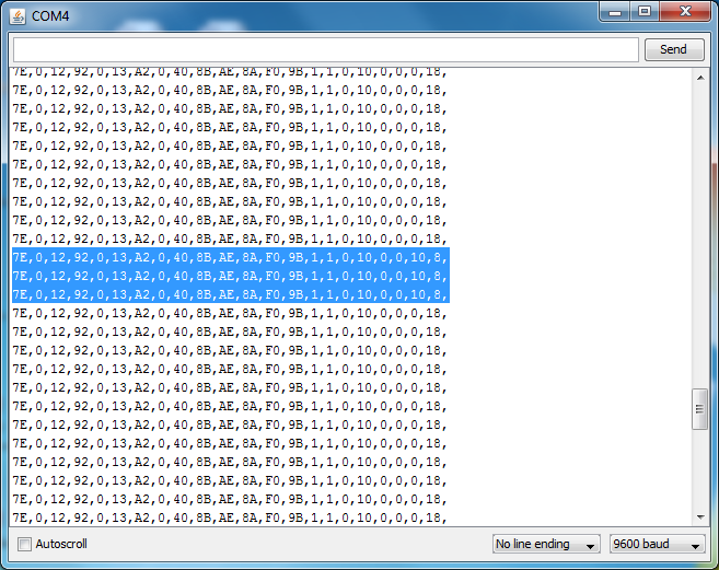
I have the arduino (XBee #1 controller) programmed to write out the frame that the XBee #2 (router) sent to it. By analyzing the frame (of hex values) we can see the digital pin being toggled as well. The highlighted lines second to the last byte (0x10) shows that digital pin 4 read high. Why 0x10 you ask? That is because bytes 19 and 20 represent the digital pin data. byte 20 represents 8 digital pins with bit 0 corresponding to digital pin 0 and bit 7 to digital pin 7. So, 0x10 (16 decimal) is 10000 in binary which tells us that digital pin 4 is reading high.
Overview
My first simple project was having 1 XBee (the coordinator in API mode) talking serial to an arduino. The second XBee (the router in AT mode) would be reading a state of a pin and reporting its value every second. It would send that information to the coordinator and the coordinator would send it to the arduino where it can be seen via the serial monitor. A contrived setup and test of the XBee, but yet it made me have to learn a few more things and research on how it works.
| XBee #1 - the controller in API mode |
| XBee #2 - the router in AT mode |
The XBee #2 (router) is hooked up to an arduino solely for power and is not using any other features on the arduino. The XBee's I/O pin has been configured (via X-CTU) to read the state of the pin every second. To change the state, I have a momentary push button and a LED wired in. Pushing the button will cause the pin to read HIGH and the LED to go on. Releasing the button will cause the pin to read LOW and the LED to go off. Here are a few more pictures to illustrate.
Understanding the data
I have the arduino (XBee #1 controller) programmed to write out the frame that the XBee #2 (router) sent to it. By analyzing the frame (of hex values) we can see the digital pin being toggled as well. The highlighted lines second to the last byte (0x10) shows that digital pin 4 read high. Why 0x10 you ask? That is because bytes 19 and 20 represent the digital pin data. byte 20 represents 8 digital pins with bit 0 corresponding to digital pin 0 and bit 7 to digital pin 7. So, 0x10 (16 decimal) is 10000 in binary which tells us that digital pin 4 is reading high.
![]() |
| State of digital pin changed |
Sunday, September 1, 2013
TFT Display
Wow, I'm so far behind with this blog! I recently got a 2.2" 18-bit color TFT Display and hooked it up to my arduino to see what the demo looks like. Quite impressive! Especially coming from a monochrome 128x64 display! To get it working using the arduino was very straight forward and simple. I want to use this with my Raspberry Pi so the next step would be to make my own C++ driver to talk to the ILI9340 chip on the TFT. Granted, not all the functionality that the arduino library will be supported, as I just to display text and a few graphics (PNG or BMP). The TFT board also has a mini sd card slot so you could store pictures or data on there that is to be displayed. Check out the link about for all the specifications for the board.
Here are a few pictures from the arduino demo.


Here are a few pictures from the arduino demo.


Sunday, August 4, 2013
Serial communication with Arduino
Been a bit busy and this is long overdue... Here is an example of serial communication between the Arduino and a computer. In this example, I'll use python to send data over the serial port. The arduino will listen and if it gets the right data, it will light up the RGB LED. Here is how things are wired.
The python script basically sends the first parameter to the serial port. In my case, the serial port i'm sending data to is /dev/tty.usbmodem1421 (this is my aruduino). The arduino acts upon 3 commands and they are "red", "green", and "blue." Anything other than those 3 commands are ignored. Here is the arduino code.
After compiling and uploading the sketch to the aruduino, we execute the python script.
If you open the serial monitor on the aruduino, you can see what the aruduino is doing. Here is a sample screenshot.
Here are the results you should see with respect to the LED.

Next up, using PWM to control the brightness of the LED of each color. Hopefully I can get this next blog post up within a few days...
I have the green pin connected to digital pin 7, the blue pin connected to digital pin 5, and the red pin connected to digital pin 3 on the arduino. One pin of the RGB LED is connected to ground. Please check your LED leads to see which is your ground pin. I also have 3 220 ohm current limiting resistors wired in. Nothing too special here... For the Arduino code, I have things driven from the serial communication. Based on what it receives, it will light up the appropriate LED color. For example, if "red" is received, the LED will light up red. If "blue" is received, it will light the LED in blue.
#!/usr/bin/env python
import serial
import sys
if (len(sys.argv) > 1):
ser = serial.Serial('/dev/tty.usbmodem1421', 9600)
bytesWritten = ser.write(sys.argv[1])
print ("bytes written: " + str(bytesWritten))
The python script basically sends the first parameter to the serial port. In my case, the serial port i'm sending data to is /dev/tty.usbmodem1421 (this is my aruduino). The arduino acts upon 3 commands and they are "red", "green", and "blue." Anything other than those 3 commands are ignored. Here is the arduino code.
#includeconst int GREEN_PIN = 7; const int BLUE_PIN = 5; const int RED_PIN = 3; int incomingByte = 0; char buf[16]; void setup () { Serial.begin(9600); pinMode(GREEN_PIN, OUTPUT); pinMode(BLUE_PIN, OUTPUT); pinMode(RED_PIN, OUTPUT); digitalWrite(GREEN_PIN, LOW); digitalWrite(BLUE_PIN, LOW); digitalWrite(RED_PIN, LOW); memset(buf, '\0', sizeof(buf)); } void loop () { if (readColorFromSerial()) { if (strcmp (buf, "red") == 0) { // change led to red Serial.println ("changing LED to red"); lightLED(RED_PIN); } else if (strcmp (buf, "green") == 0) { // change led to green Serial.println ("changing LED to green"); lightLED(GREEN_PIN); } else if (strcmp (buf, "blue") == 0) { // change led to blue Serial.println ("changing LED to blue"); lightLED(BLUE_PIN); } else { Serial.print("Invalid input '"); Serial.print(buf); Serial.println("' - expected red, green, or blue"); } } } int readColorFromSerial() { if (Serial.available()) { memset(buf, '\0', sizeof(buf)); Serial.readBytesUntil('\n', buf, sizeof(buf)); return 1; } return 0; } void lightLED(int pin) { switch (pin) { case RED_PIN: digitalWrite(GREEN_PIN, LOW); digitalWrite(BLUE_PIN, LOW); digitalWrite(RED_PIN, HIGH); break; case GREEN_PIN: digitalWrite(BLUE_PIN, LOW); digitalWrite(RED_PIN, LOW); digitalWrite(GREEN_PIN, HIGH); break; case BLUE_PIN: digitalWrite(RED_PIN, LOW); digitalWrite(GREEN_PIN, LOW); digitalWrite(BLUE_PIN, HIGH); break; } }
After compiling and uploading the sketch to the aruduino, we execute the python script.
If you open the serial monitor on the aruduino, you can see what the aruduino is doing. Here is a sample screenshot.
Here are the results you should see with respect to the LED.

Next up, using PWM to control the brightness of the LED of each color. Hopefully I can get this next blog post up within a few days...
Labels:
arduino
Saturday, July 13, 2013
Raspberry Pi GPIO with RGB LED
I was playing around more with the wiringPi library and a Red Green Blue LED. I have a simple setup that will blink the led in each color. From the video, it's a bit tough to distinguish between blue and green so I included a few pictures of each color as well.
Tuesday, July 9, 2013
Ubuntu on BeagleBone Black
After playing around with Angstrom, I wanted to try my hand at Ubuntu so I decided to flash my BBB with the Ubuntu wheezy image. The process was relatively painless and I was about to write up what I did, but I came across a post that was very similar to my steps so I'll link that one instead.
http://avedo.net/653/flashing-ubuntu-13-04-or-debian-wheezy-to-the-beaglebone-black-emmc/
Now that I am on familiar ground, I was able to port over my code for the OLED and GPS to the BBB. Though I haven't wired it all up yet, I was able to compile it without issues. I actually waiting for another breadboard that I ordered so I won't have to tear down what I currently have just to test my BBB setup.
http://avedo.net/653/flashing-ubuntu-13-04-or-debian-wheezy-to-the-beaglebone-black-emmc/
Now that I am on familiar ground, I was able to port over my code for the OLED and GPS to the BBB. Though I haven't wired it all up yet, I was able to compile it without issues. I actually waiting for another breadboard that I ordered so I won't have to tear down what I currently have just to test my BBB setup.
Labels:
bbb
,
beaglebone
Monday, July 8, 2013
GPIO using the Raspberry Pi
After getting my OLED and GPS working, I wanted to mess around with the GPIO pins so I bit off something simple. Here is what my setup looks like.
- Raspberry Pi
- Raspberry Pi T Cobbler
- Raspberry Pi Ribbon Cable
- Breadboard
- Two 1 KiloOhms resistors
- Two 10 KiloOhms resistors - pull up resistors
- 2 momentary pushbuttons
- Jumper wires
In this setup, pushing the button will drive the signal low. To keep things simple and just illustrate the point, pushing the button(s) will just print out a message to stdout. In doing some research, I came across Gordon's wiringPi library. I incorporated this into my code so I didn't have to reinvent the wheel! It is pretty simple to use for my C++ application. I started out the simple way and had a loop to check the pin status and act upon it if it has changed. However, that doesn't fit my end goal so I got a bit fancier with the implementation, but the good news is that it is supported by wiringPi. The fancier implementation is to use interrupts and to have a function pointer called when the interrupt is detected. Below is the code to drive this circuit. Currently, the circuit does bounce so debouncing code will need to be added to normalize this, but hopefully this illustrates the point.
#include <iostream>
#include <wiringpi.h>
// These are wiringPi pin numbers from http://wiringpi.com/pins
#define BUTTON_1 7 // pin 7 on pi
#define BUTTON_2 3 // pin 15 on pi
using namespace std;
void interruptHandler ()
{
cout << "in interruptHandler()" << endl;
}
void interruptHandler2 ()
{
cout << "in interruptHandler2()" << endl;
}
int main ()
{
if (wiringPiSetup() < 0)
{
cout << "uniable to initialize wiringPi library!" << endl;
return 1;
}
if (wiringPiISR (BUTTON_1, INT_EDGE_FALLING, &interruptHandler) < 0)
{
cout << "Unable to register interrupt handler for BUTTON_1!" << endl;
return 1 ;
}
if (wiringPiISR (BUTTON_2, INT_EDGE_FALLING, &interruptHandler2) < 0)
{
cout << "Unable to register interrupt handler for BUTTON_2!" << endl;
return 1 ;
}
// wait for interrupt, but don't consume 100% of cpu
while (1)
delay (100);
return 0;
}
Tuesday, July 2, 2013
Raspberry Pi GPS and LCD
The OLED is connected via I2C to the Raspberry Pi and the GPS is using the hardware UART on the Pi. The hard part is now out of the way! Next up, save the GPS data (in KML) to a file and plot that file on Google Earth.
Sunday, June 30, 2013
Hanging Lake Hike
It's been long overdue, but we finally made it to Hanging Lake Trail in Glenwood Springs, CO. Once we got there, the parking was full as it usually is on weekends! When we finally got to the trailhead, we noticed this sign. It's a bit misleading since there were many kids and many families carrying young ones so "difficult" does not really apply.
The hike is about a 1000 ft ascend and is about 1.1 miles one way. The views are very nice and the pictures below do not do it justice!
The forecast was for 92 degrees, but we lucked out as going up a passing storm went by and dropped some rain which made it much cooler.
Here are some pictures from the beginning of the trail.
For the most part, the trail consists of rock, but there are some areas where it's either gravel or dirt.
Some nice views of Glenwood Canyon are visible from the trail as well.
At the top, there is a nice view of a waterfall. Going a bit past it to Spouting Rock yields a nice waterfall and can cool you off!
Labels:
hiking
Subscribe to:
Posts
(
Atom
)