Sunday, February 23, 2014

avr-gcc adafruit trinket example

I've been interested in learning more about programming microcontrollers and saw that Adafruit has a low cost board (called trinket) that is very convenient since it can be programmed over USB. When I first got my hands on this, I was making sketches for it using the Arduino IDE, but wanted to dive in at a lower level and be able to write C code and reprogram the Attiny85 chip that is on board. There are many different ways to do this, but here is the way I went about doing it.

Install the following packages
sudo apt-get update
sudo apt-get install gcc-avr gdb-avr binutils-avr avr-libc avrdude

You should now have an environment that you can compile and link code for Atmel microprocessors. The last package (avrdude) is what we will use to program the chip. Here is an example of how to blink the LED on pin 1 of the trinket (the red LED).

// blink.c
#include <avr/io.h>
#include <util/delay.h>

// prototype
void wait_sec(int seconds);

int main (void)
{
   // direction register
   DDRB |= 0x03; // pin 0 and pin1 as output
   while(1)
   {
      PORTB |= 0x02; // LED ON
      wait_sec(1); // sleep
      PORTB &= 0x01; // LED OFF
      wait_sec(1); // sleep
   }
   return 0;
}

// sleeps the specified amount of seconds
void wait_sec(int seconds)
{
   int i;
   for(i=0; i<seconds; i++)
      _delay_ms(1000);
}

You can compile the code with avr-gcc. At the time of writing this post, I'm using avr-gcc version 4.7.2. For this contrived example, I will not create a makefile, but it's usually good practice to do so.

avr-gcc -I. -I. -g -mmcu=attiny85 -DF_CPU=8000000UL -Os -fpack-struct -fshort-enums -funsigned-bitfields -funsigned-char -Wall -Wstrict-prototypes -Wa,-ahlms=blink.lst -c blink.c -o blink.o
avr-gcc -Wl,-Map,myproject.out.map -mmcu=attiny85 -lm  -o myproject.out blink.o 
avr-objcopy -j .text                    \
  -j .data                       \
  -O ihex myproject.out myproject.hex
avr-objcopy -j .eeprom                  \
  --change-section-lma .eeprom=0 \
  -O ihex myproject.out myproject.ee.hex
avr-objcopy: --change-section-lma .eeprom=0x0000000000000000 never used

If things went smoothly, you should now have a file called myproject.hex. This is the binary we will program the chip with using avrdude. To program the trinket, press the reset button so the red LED blinks which signifies it's in bootloader mode. Execute the following to upload and program the chip.
sudo avrdude -c usbtiny -p attiny85 -U flash:w:myproject.hex

avrdude: AVR device initialized and ready to accept instructions

Reading | ################################################## | 100% 0.00s

avrdude: Device signature = 0x1e930b
avrdude: reading input file "myproject.hex"
avrdude: input file myproject.hex auto detected as Intel Hex
avrdude: writing flash (116 bytes):

Writing | ############################                       | 55% 0.03savrdude: 6 retries during SPI command
Writing | ################################################## | 100% 0.07s


avrdude: 116 bytes of flash written
avrdude: verifying flash memory against myproject.hex:
avrdude: load data flash data from input file myproject.hex:
avrdude: input file myproject.hex auto detected as Intel Hex
avrdude: input file myproject.hex contains 116 bytes
avrdude: reading on-chip flash data:

Reading | ################################################## | 100% 0.01s


avrdude: verifying ...
avrdude: 116 bytes of flash verified

avrdude: safemode: Fuses OK

avrdude done.  Thank you.
Once the chip is programmed, you should see the blink code running.

Sunday, February 9, 2014

I2C Library for BBB and Pi

I've been getting numerous requests to share my I2C Library. There are a few other things I'm adding to my github repository before I publish it, but in the meantime, here is the I2C library. Using and/or downloading it means you do so at your own risk.

This is nothing fancy as I only did what I needed to for my projects. This library works on both Raspberry Pi and BeagleBone Black for my Adafruit 128x64 OLED module.

i2c.cpp and i2c.h

Tuesday, September 10, 2013

Beaglebone Black with 128x64 OLED

I compiled my I2C OLED library on my beaglebone black and with little effort, I was able to get it working. My BBB is running Ubuntu instead of Angstrom (instructions to get that flashed are in a previous post). This code was the same one running on the raspberry pi in my prior posts.

Steps taken were:
  1. Download code from github
  2. run make
  3. run the compiled executable
The I2C class was defaulted to use the address of the OLED so I didn't need to change anything. :)

Here are some images of displaying a BMP on the OLED.

Monday, September 2, 2013

Simple Xbee Tutorial

I also got a few XBee modules with USB XBee Adapters and I started to mess around with them. The reason I got the adapters is primarily two fold. First, the XBee pins are 2mm and not the standard 0.1" so they do not fit on the standard breadboard. Secondly, the USB adapter makes programming the XBee very simple. I am using X-CTU to do the programming, but you can also do it over command line using the terminal, but it's a little more complicated.

Overview
My first simple project was having  1 XBee (the coordinator in API mode) talking serial to an arduino. The second XBee (the router in AT mode) would be reading a state of a pin and reporting its value every second. It would send that information to the coordinator and the coordinator would send it to the arduino where it can be seen via the serial monitor. A contrived setup and test of the XBee, but yet it made me have to learn a few more things and research on how it works.


XBee #1 - the controller in API mode
XBee #2 - the router in AT mode


The XBee #2 (router) is hooked up to an arduino solely for power and is not using any other features on the arduino. The XBee's I/O pin has been configured (via X-CTU) to read the state of the pin every second. To change the state, I have a momentary push button and a LED wired in. Pushing the button will cause the pin to read HIGH and the LED to go on. Releasing the button will cause the pin to read LOW and the LED to go off. Here are a few more pictures to illustrate.

Understanding the data
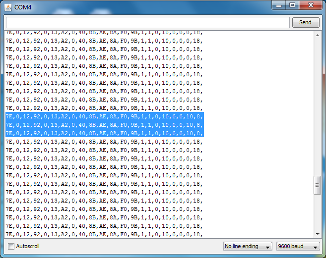
I have the arduino (XBee #1 controller) programmed to write out the frame that the XBee #2 (router) sent to it. By analyzing the frame (of hex values) we can see the digital pin being toggled as well. The highlighted lines second to the last byte (0x10) shows that digital pin 4 read high. Why 0x10 you ask? That is because bytes 19 and 20 represent the digital pin data. byte 20 represents 8 digital pins with bit 0 corresponding to digital pin 0 and bit 7 to digital pin 7. So, 0x10 (16 decimal) is 10000 in binary which tells us that digital pin 4 is reading high.
State of digital pin changed

Sunday, September 1, 2013

TFT Display

Wow, I'm so far behind with this blog! I recently got a 2.2" 18-bit color TFT Display and hooked it up to my arduino to see what the demo looks like. Quite impressive! Especially coming from a monochrome 128x64 display! To get it working using the arduino was very straight forward and simple. I want to use this with my Raspberry Pi so the next step would be to make my own C++ driver to talk to the ILI9340 chip on the TFT. Granted, not all the functionality that the arduino library will be supported, as I just to display text and a few graphics (PNG or BMP). The TFT board also has a mini sd card slot so you could store pictures or data on there that is to be displayed. Check out the link about for all the specifications for the board.

Here are a few pictures from the arduino demo.

Sunday, August 4, 2013

Serial communication with Arduino

Been a bit busy and this is long overdue... Here is an example of serial communication between the Arduino and a computer. In this example, I'll use python to send data over the serial port. The arduino will listen and if it gets the right data, it will light up the RGB LED. Here is how things are wired.
I have the green pin connected to digital pin 7, the blue pin connected to digital pin 5, and the red pin connected to digital pin 3 on the arduino. One pin of the RGB LED is connected to ground. Please check your LED leads to see which is your ground pin. I also have 3 220 ohm current limiting resistors wired in. Nothing too special here... For the Arduino code, I have things driven from the serial communication. Based on what it receives, it will light up the appropriate LED color. For example, if "red" is received, the LED will light up red. If "blue" is received, it will light the LED in blue.


#!/usr/bin/env python

import serial
import sys

if (len(sys.argv) > 1):
    ser = serial.Serial('/dev/tty.usbmodem1421', 9600)
    bytesWritten = ser.write(sys.argv[1])
    print ("bytes written: " + str(bytesWritten))

The python script basically sends the first parameter to the serial port. In my case, the serial port i'm sending data to is /dev/tty.usbmodem1421 (this is my aruduino). The arduino acts upon 3 commands and they are "red", "green", and "blue." Anything other than those 3 commands are ignored. Here is the arduino code.
#include 

const int GREEN_PIN = 7;
const int BLUE_PIN = 5;
const int RED_PIN = 3;

int incomingByte = 0;
char buf[16];

void setup ()
{
  Serial.begin(9600);
  pinMode(GREEN_PIN, OUTPUT);
  pinMode(BLUE_PIN, OUTPUT);
  pinMode(RED_PIN, OUTPUT);

  digitalWrite(GREEN_PIN, LOW);
  digitalWrite(BLUE_PIN, LOW);
  digitalWrite(RED_PIN, LOW);
  memset(buf, '\0', sizeof(buf));
}

void loop ()
{
  if (readColorFromSerial())
  {
    if (strcmp (buf, "red") == 0)
    {
      // change led to red
      Serial.println ("changing LED to red");
      lightLED(RED_PIN);
    }
    else if (strcmp (buf, "green") == 0)
    {
      // change led to green
      Serial.println ("changing LED to green");
      lightLED(GREEN_PIN);
    }
    else if (strcmp (buf, "blue") == 0)
    {
      // change led to blue
      Serial.println ("changing LED to blue");
      lightLED(BLUE_PIN);
    }
    else
    {
      Serial.print("Invalid input '");
      Serial.print(buf);
      Serial.println("' - expected red, green, or blue");
    }
  }
}

int readColorFromSerial()
{
  if (Serial.available())
  {
    memset(buf, '\0', sizeof(buf));
    Serial.readBytesUntil('\n', buf, sizeof(buf));
    return 1;
  }
  return 0;
}

void lightLED(int pin)
{
  switch (pin)
  {
  case RED_PIN:
    digitalWrite(GREEN_PIN, LOW);
    digitalWrite(BLUE_PIN, LOW);
    digitalWrite(RED_PIN, HIGH);
    break;
  case GREEN_PIN:
    digitalWrite(BLUE_PIN, LOW);
    digitalWrite(RED_PIN, LOW);
    digitalWrite(GREEN_PIN, HIGH);
    break;
  case BLUE_PIN:
    digitalWrite(RED_PIN, LOW);
    digitalWrite(GREEN_PIN, LOW);
    digitalWrite(BLUE_PIN, HIGH);
    break;
  }
}

After compiling and uploading the sketch to the aruduino, we execute the python script.


If you open the serial monitor on the aruduino, you can see what the aruduino is doing. Here is a sample screenshot.

Here are the results you should see with respect to the LED.
Next up, using PWM to control the brightness of the LED of each color. Hopefully I can get this next blog post up within a few days...

Saturday, July 13, 2013

Raspberry Pi GPIO with RGB LED

I was playing around more with the wiringPi library and a Red Green Blue LED. I have a simple setup that will blink the led in each color. From the video, it's a bit tough to distinguish between blue and green so I included a few pictures of each color as well.